Magnetic gears are surprisingly unknown and used only in a few niche applications. Yet, their popularity is on the rise, and they are one of the slickest solutions for transmitting mechanical energy, converting rotational torque and RPM. Sooner or later, you’re bound to stumble upon them somewhere, so let’s check them out to see what they are and what they are good for.
What Are Magnetic Gears?
Where conventional gears use mating surfaces of mechanical interlocking teeth, magnetic gears employ alternating magnetic fields to transmit torque. For a long time, magnetic gears have only played a minor role in engineering. Their comparably high price, directly reflecting their dependence on rare earths like Neodymium, complex assemblies,and their tendency to slip at high torques hasn’t exactly pushed them into the spotlight. The achievable torque density of magnetic gears is indeed considerably lower than the one of their mechanical counterparts, although, on the plus side, they also do not suffer irreparable damage if their specified torque is exceeded. Currently, increasing the torque in magnetic gears is the subject of many research programs, and magnetic gears are finding their way into more applications.
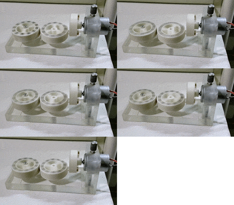
Because magnetic gears aren’t mechanically interlocking, with no physical contact between any of the rotors, they are not subject to mechanical wear. Most regular gear types, such as cogwheels and even worm gears, can be replicated as magnetic gears, simply by replacing the cut teeth with alternating magnetic poles of permanent magnets. The 3D printed, magnetic “cog wheel” assembly to the right is a great example of this.
However, in industrial applications, the term magnetic gear often implies a far better performing coaxial type, which you can see in the animations below. It is structurally very similar to a strain wave gear (i.e. the Harmonic Drive gear, also shown below) and allows for high gear ratios as well as comparably high torque. This type of gear relies on the flexibility of the magnetic field rather than on a flexible spline. Click on the animations of different gears below to see details about how they work:


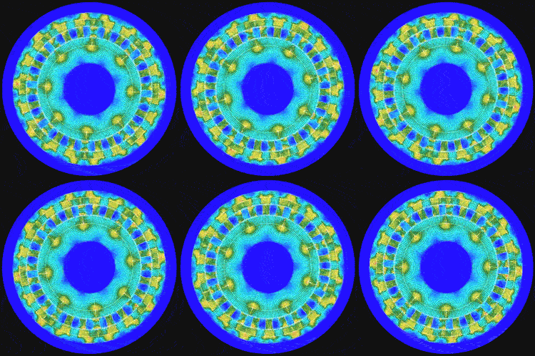
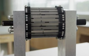
As the inner, fast spinning magnet ring of the concentric, magnetic gear rotates, it forces the modulator ring, consisting of ferromagnetic steel pieces embedded in a non-magnetic tray, to mesh with the alternating magnetic field of the outer ring. Both the inner and outer ring are assembled from strong permanent magnets, and the numbers of pole pairs in the inner and outer ring as well as the number of iron pieces set the gear ratio. Due to the small air gap between all rings, there is no friction to account for. The actual implementation of such a gear may vary, and the modulator ring may either act as a stator or can be directly attached to the output shaft, with the outer magnet ring then acting as a stator.
Coaxial magnetic gears can be extraordinarily efficient, almost maintenance free, have a very low torque ripple and find applications were those factors are an issue. At low speeds, they achieve efficiencies in the range of 99.9 %. The high gear ratio of magnetic gears makes them interesting for stepping up very slow input forces, such as ocean wave power, an application that has been explored by the UNC Coastal Studies Institute. The same benefits make them interesting for wind turbines as well.
Another application for magnetic gears is marine propulsion, where they are used to step down higher input RPM from an engine to the low RPM and high torque required for the propeller shaft. Earlier this year, Rolls-Royce, ATB Laurence Scott and magnetic gearbox manufacturer Magnomatics announced their plans to develop a magnetically geared propulsion system for ships. The ability of magnetic gears to hermetically seal the input and output forces is also useful in laboratory and medical environments.

Of course, magnetic gears have disadvantages, too. As mentioned, the maximum torque may not be sufficient for some applications, and they are expensive and typically heavier than regular gears. Also, at very high RPM, they lose their advantage of efficiency due to increased losses, caused by hysteresis and increased eddy currents in the modulator. Nevertheless, most of these limitations are slowly being removed by ongoing research. The programmable magnets by CMR allow for strong, fine pitched magnetic structures, which may allow for smaller, more efficient magnetic gears with higher torque density in the future. Also, the requirements for gears are changing. While more torque may always be better in industrial applications, interactive robotic applications require mechanisms that give in and ensure the safety of human users.
Magnetic gears can also be fabricated without the need for heavy gear-cutting machinery, which makes them especially interesting for DIY projects. A decent, concentric magnetic gear could be assembled from a bunch of permanent magnets, easily available hardware and 3D printed parts. What do our readers think, would you use a magnetic gear for a project? Did you encounter magnetic gears in applications I’ve missed here? Let us know and share your ideas in the comments!
Thanks to [Ralph Bijker] for creating the cog wheel rendering used in the header graphic!
- originally appeared on hackaday.com


